

HSMWorks tutorial №1 - 2D Machining


𝐃𝐢𝐬𝐜𝐥𝐚𝐢𝐦𝐞𝐫: This tutorial is a representation of the original Help tutorial, which Autodesk ships with the HSMWorks software suite.
This guide is intended for educational purposes and to make the features and tools of HSMWorks more accessible to the general public.
More information about purchasing, installing, and using HSMWorks can be found on the official website: https://www.autodesk.com/products/hsmworks
𝐓𝐮𝐭𝐨𝐫𝐢𝐚𝐥 𝟏 - 𝟐𝐃 𝐌𝐚𝐜𝐡𝐢𝐧𝐢𝐧𝐠
In this tutorial you will learn how to machine the part through the following steps:
▸ Facing
▸ Contouring
▸ Pocket Machining
▸ Counterboring
▸ Drilling
▸ Tapping
▸ Post Processing
Before proceeding, please open the part "Tutorial1.SLDPRT" into HSMWorks, by choosing "Open" from the File menu, and then browsing to the file.
-
Step 1: Facing
To clear the top face of our stock and ensure that it is completely horizontal, we will begin with a facing operation.
➝ Click Face on the CAM toolbar or select it form the CAM, Toolpaths menu.
This creates a new operation and opens the Property Manager where you can edit the individual parameters controlling the toolpath, as well as selecting the actual geometry to machine.
The property page is divided into number of groups, and in this tutorial we will go through each one by one changing the necessary settings in each group as we go along.
1. Tool
➝ Press Library
➝ From the library Tutorial under Sample Libraries, select tool #1 - Ø50mm face
➝ Press Select
2. Geometry
By default, the Face strategy automatically detects the contour of the stock, which is shown as an orange outline on the part.

In this example the default stock and stock contours will work fine, and we don't need to specify the stock contours manually.
3. Passes
The parameters in this group controls how the actual facing toolpath is laid out.
When you selected the 50mm tool, the Stepover and Pass Extension parameter were automatically updated to reflect the new tool diameter. We will leave the parameters at their defaults, except the pass extension, which we can increase.
➝ Change Pass Extension to 5 mm
4. Start calculations
➝ Click ✓ at the top of the property manager.
This will automatically start calculation of the toolpath.
The toolpath will now be calculated and a preview will be shown in the model view:

By default the cutting parts of a toolpath are colored in blue, lead moves in green and rapid moves in yellow. The start and end of the toolpath are indicated by a red and a green triangle respectively.
-
Step 2: Contouring
Next, we will run a contouring toolpath along the outside of the part.
➝ Click 2D Contour on the CAM toolbar or select it from the CAM, Toolpaths menu, under 2D Milling.
1. Tool
➝ Press Library
This opens the Tool Library where you can select from existing tools in a library or define a new tool.
Tool definitions can be saved in a library or just for the part you work on. In this example we will save the tools in the part only. You can always copy the tools to a library at a later time, if you wish to re-use them
Add a new tool with default dimensions:
➝ Press New Mill Tool
We can use the default tool type and dimensions (a 10mm flat mill) for this tutorial, but we will increase the flute length be able to cut the entire height of the part (22mm):
➝ Click the Cutter tab
➝ Change Flute Length to 25mm.
➝ Press the OK button to create your new tool.
➝ Press the Select button to select the tool for your operation and close the tool dialog.
If you decide to execute this toolpath on a machine tool, ensure that the tool number corresponds with the tool position in your tool changer on the machine tool, ie. that on position 6 you have a 10mm flat end mill cutter.
In the Feed & Speed group, change the following parameters:
➝ Spindle Speed: 3000rpm
➝ Cutting Feedrate: 800mm/min
If you decide to execute this toolpath on a machine tool, you will also need to set the feed & speed parameters according to the material you are using, and the capabilities of your tool and machine.
2. Geometry
Here we select the geometry we want to machine. We want to run the tool around the outside edge of the part.
Select the edges to be machined. Move the mouse over the bottom front edge, it will be highlighted, then click on it. Depending on the side of the edge you click you can determine the direction of the contour. By clicking closer to the desired start of an edge you can determine the direction of the contour. For climb milling click close to the bottom right side of the edge.
You can reverse the direction of a selected edge either by de-selecting it and clicking near the opposite end, or alternatively by pressing Reverse in the property manager.
After you finished your geometry selections, the graphics window should look like this:

3. Heights
When activating the Heights tab, a preview of the heights will be shown:
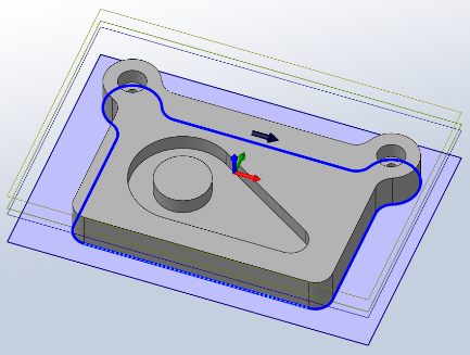
Preview of heights:
• The top yellow plane represents the clearance height.
• The second yellow plane represents the retract height.
• The green plane represents the feed height.
• The top blue plane is the top.
• The second blue plane is the bottom.
To make sure that the tool gets all the way through the stock, we can lower the bottom height by 1 mm.
➝ Bottom: -1.0mm
Note that the preview plane moves.
4. Start calculation
Click ✓ at the top of the property manager.
The toolpath will now be calculated and shown in the graphic area.

Notice that in the operation manager a new job has been created automatically. This is automatically done when creating a new operation before a job has been created. A job defines a number of settings used in all the operations contained within the job. For example the WCS can be changed in the Job.
-
Step 3: Pocket Machining
We want to machine the pocket with the central circular boss on the top surface of the part.
➝ Click 2D Pocket on the CAM toolbar or select it from the CAM, Toolpaths menu, under 2D Milling.
1. Tool
By default the last tool used will be selected. Ensure that the tool #2 - Ø10mm flat is selected.
2. Geometry
Here we select the contours of the pocket we want to clear.
Click anywhere on the face at the bottom of the pocket.

Selecting faces for 2D geometry automatically uses all edges of the face for the contours. If two adjacent faces are selected, the edges they share are, however, not included in the selection.
3. Heights
By default, the 2D Pocket operation machines from the top of stock to the level of the selected contours. This is exactly what we need in this operation so there is no need to change any heights.
4. Passes
This group controls how the 2D pocket toolpath will be calculated. We want to use this pocket toolpath to clear out the pocket. To do this we want to generate the toolpath in a number of Z levels, starting from the top of the stock and going down in steps of 2 mm to the bottom of the pocket.
➝ Enable Multiple Depths
➝ Change Maximum Roughing Stepdown: 2.0mm
➝ Change Finishing Stepdowns: 1
We do not want to leave any stock in this operation, and since this is a roughing operation, the default is to leave stock.
➝ Disable Stock To Leave
5. Start calculation
➝ Click ✔ at the top of the property manager.
The toolpath will now be calculated and shown in the graphic area.

-
Step 4: Counterboring
The next step is to machine the two counterbores at the top left and right corners of the part.
➝ Click Bore on the CAM toolbar or select it from the CAM, Toolpaths menu, under 2D Milling.
1. Tool
By default the last tool used will be selected. Ensure that the tool #2 - Ø10mm flat is selected.
2. Geometry
Here we select the cilindrical faces of the two holes with the widest diameter at the top corners of the part.
➝ Zoom in, and click anywhere on the cilindrical surface of the upper big hole.

➝ Do the same to select the other hole in the opposite corner.
3. Passes
Here we can control how the helix toolpath will be calculated.
Bore
➝ Change Pitch: 2 mm
4. Start calculation
➝ Click ✔ at the top of the property manager.
The toolpath will now be calculated and shown in the graphic area.

-
Step 5: Drilling
Now we want to drill the two holes at the top left and right corners of our work piece.
Click Drill on the CAM toolbar or select it from the CAM, Toolpaths menu.
1. Tool
Change the default tool:
➝ Press Library to open the Tool Library.
➝ Click New Mill Tool
This will create a tool with default dimensions and cutting data. The default is a 10mm flat mill. We will use most of the defaults, but change some of the cutting parameters a bit:
➝ Click the Cutter tab.
➝ Change Type to Drill by selecting it from the drop down.
➝ Change Diameter to 5mm.
➝ Press the OK button to create your new tool.
➝ Press the Select button to select the tool for your operation and close the tool dialog.
2. Geometry
➝ Zoom in, and select one the cylindrical faces of the two holes at the top corners of the part.
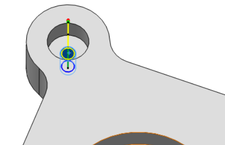
Notice that as you select the cylindrical face, the status bar will show the diameter and height of the selected face. This is helpful if you don't know in advance the size of the tool needed.
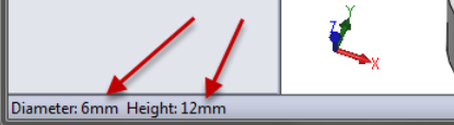
➝ Enable Select Same Diameter

3. Heights
➝ Enable Drill Tip Through Bottom:
➝ Change Break-Through Depth: 1 mm
4. Passes
Select Chip breaking - partial retract from the Cycle Type drop down.
5. Starts calculations
➝ Click ✔ at the top of the property manager.
-
Step 6: Tapping
This tapping operation only differs in the type of cycle from the previous drilling operation; tapping will be done for the same geometry. To save all the work of entering this data, we will just copy the existing drilling toolpath and create the tapping toolpath by editing this copy.
➝ Right-click on the operation Drill1.
➝ Choose Duplicate from the context menu.
➝ Right-click on the new operation.
➝ Choose Rename.
➝ Enter a new name, such as "Tapping M6".
Next we have to edit the tool and parameters.
➝ Right-click on on the operation Tapping M6.
➝ Choose Edit from the context menu.
1. Tool
To create and select a new tapping tool:
➝ Press Library to open the Tool Library.
➝ Click New Mill Tool
On the General tab:
➝ Change Number to 8.
On the Cutter tab:
➝ Change Tool type to Tap (Right Hand).
➝ Change Diameter to 6mm.
➝ Change Flute length to 15mm.
On the Feed & Speed tab:
➝ Change Spindle speed to 400rpm.
➝ Press the OK button to create your new tool.
➝ Press the Select button to select the tool for your operation and close the tool dialog.
If you want to run this toolpath on your machine tool, you may also need to set the Pitch parameter on the Cutter tab, as well as adjust the feed and speed parameters. You should always look up the correct values in your tool manufacturer catalog.
2. Passes
Now, make this a tapping cycle instead of a drilling cycle:
➝ In the group Cycle select Tapping
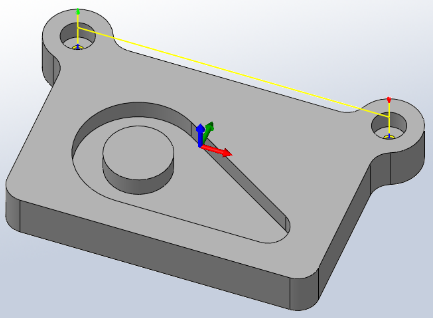
3. Start calculations
Click ✔ at the top of the property manager. The resulting toolpath will look like this:

You have now finished all operations in this tutorial.
-
Step 7: Post Processing
It is good practice before you start the post processing to regenerate all toolpaths and then simulate the toolpaths. This way you can spot any errors in the toolpaths and rectify them.
We are ready to post process all toolpaths in order to make the NC-code which can be used by the machine tool.
➝ Right-click on Job in the operation manager.
➝ Select Post Process (All).
➝ From the pull down Post processor configuration select heidenhain.cps - Generic Heidenhain
➝ Select an output folder of your choice.
➝ Start the post processor by clicking Post. By default the post processed file will be loaded into HSMWorks Edit.
You can also post process individual operations by invoking the post processor through a right-click on the operation, and selecting Post Process from the context menu.
Congratulations! You have completed this tutorial.